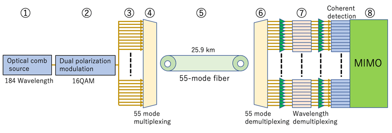
Figure 7 Schematic diagram of the newly developed transmission system (circled numbers refer to Figure 1).
Figure 7 shows a schematic diagram of the newly developed transmission system.
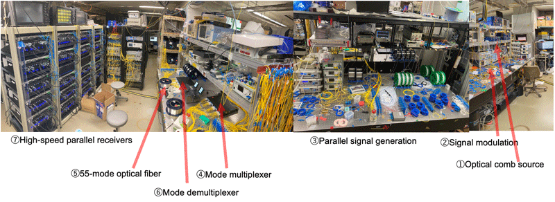
① Optical comb source: 184 carriers are generated in a single optical comb source.
② Signal modulation: Carriers are modulated with 16 QAM signals and polarization multiplexed.
③ Parallel signal generation: Signals are branched for each mode, and path delays are applied to emulate independent data streams.
④ Mode multiplexer: Each signal is transformed into a different spatial mode and launched into a 55-mode optical fiber.
⑤ 55-mode optical fiber: Signals propagate through a 25.9 km long 55-mode optical fiber.
⑥ Mode demultiplexer: Signal for each spatial mode at the receiver side is separated and transformed into a fundamental mode.
⑦ High-speed parallel receivers: The mode-demultiplexed signals are wavelength-demultiplexed by filters and converted into electrical signals by parallel coherent receivers.
⑧ Off-line signal processing: MIMO processing to eliminate signal interference during fiber propagation.


 ml.nict.go.jp