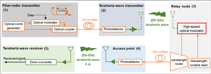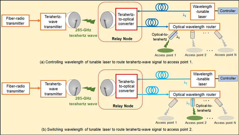
Figure 4 Schematic diagram for transparent terahertz-wave signal relay and switching.
Figure 4 shows a schematic of the proposed system, which includes five main parts: a fiber-radio transmitter, a terahertz-wave radio transmitter, a relay node, an access point, and a terahertz-wave receiver.
(1) Fiber-radio transmitter
This block generates and modulates signals. An optical frequency comb signal was generated using a single dual-drive optical modulator. Two comb lines with a frequency difference of 275.2 GHz were selected, one of which was modulated using an OFDM signal at 9.8 GHz. The bias voltage applied to the modulator was controlled to generate only the upper modulation sideband. The modulated and unmodulated signals were combined to form a 285-GHz radio-over-fiber (RoF) signal.
(2) Terahertz-wave radio transmitter
After transmission over a 20-km single-mode fiber, the RoF signal was up-converted to a 285-GHz terahertz-wave signal using a high-speed photodetector. The generated radio signal was amplified and could be emitted into free space using a terahertz-wave antenna. For simplicity, the terahertz-wave signal was connected directly to the terahertz-optical converter at the relay node.
(3) Relay node
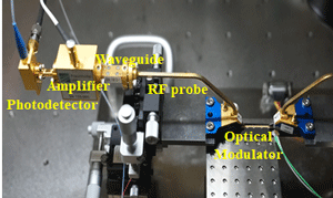
The terahertz-wave signal could be received using a terahertz-wave antenna. In the demonstration, the signal was received using a waveguide and connected to the developed optical modulator using an RF probe for conversion into an optical signal. Optical carrier signals from a wavelength-tunable laser were connected to the optical modulator for signal modulation. The modulated optical signals were connected to a wavelength router for transport to different access points, where specific wavelengths are assigned.
(4) Access point
The signal was input to another high-speed photodetector to convert it back to a terahertz-wave signal in the 285-GHz band. The signal was amplified and transmitted into free space using a 48-dBi lens antenna.
(5) Terahertz-wave receiver
The terahertz-wave signal was received using another lens antenna, amplified, and downconverted to 10.2 GHz using a subharmonic mixer. Finally, the signal was amplified, sent to a real-time oscilloscope, and demodulated.


 ml.nict.go.jp